Introduction
This document describes the iOptron CEM 25P – RA axle bearings replacement of a pair of RA axis bearings in an iOptron CEM 25P mount. This DIY document certainly does not cover the topic exhaustively, but I have tried to include as much information as I was able to gather during the bearing replacement.
Description of the problem: during rotation, bearings liked to “brake” the entire RA axis. The symptom was present permanently especially at the temperature of 25C++
After disassembling the RA axis and removing both bearings, when rotating them by hand, a slight resistance could be felt in some places. These were either defective products or factory-induced damages acquired during product assembly.
The revealed defects had to be eliminated by replacing the faulty parts with new, high-quality ones. The method of dismantling the old bearings and installing the new ones is described below.
ATTENTION!
The following steps require a certain level of skill. If you do not feel confident, it is better to entrust the mount to someone who has experience in “tinkering” and will not find it difficult to perform all the steps described below. Be aware that this description is certainly not error-free. I take no responsibility for any damage resulting from the use of this document. You perform all actions at your own risk.
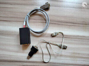
Necessary tools and some chemicals
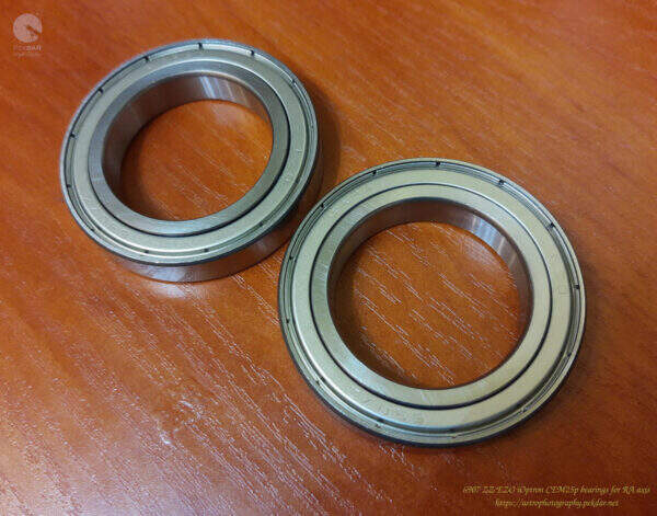
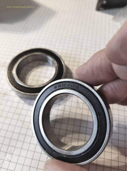
New bearings, model: 6907 ZZ EZO, 2 pcs per axis.
Multipurpose lithium grease CX80

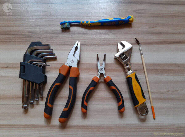
A set of auxiliary tools:
- Allen key set,
- a small toothbrush,
- pliers,
- small angled pliers,
- small wrench,
- a small art brush,
- metal hammer
Disassembly of the components of the RA axis
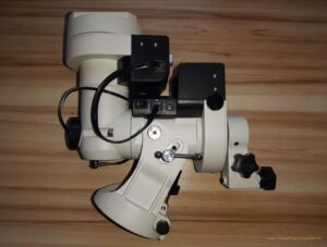
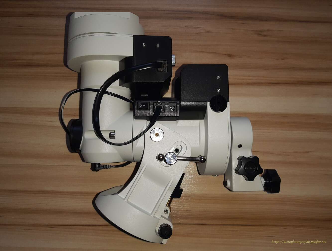
Take a picture of the assembled mount, just before taking any action, so that after disassembling it into parts, you will know what state you should return to.

Remove both caps of the polar finder.
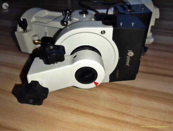
Manually unscrew the eyepiece of the polar finder.

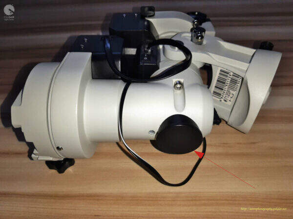
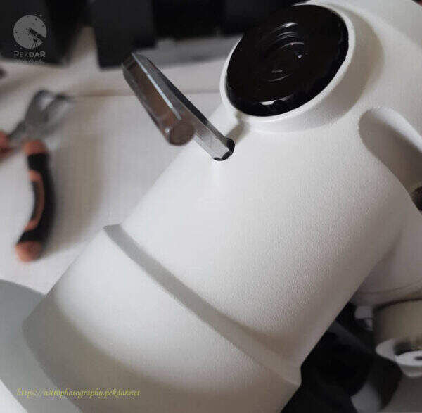
Remove the DEC body cap using the small angled pliers.

Unscrew the polar finder illuminator using the small angled pliers. Remember to not squeeze much the illuminator housing. Be gentle.

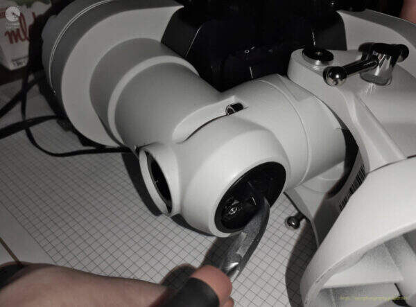
Remove the two outer bolts connecting the DEC body to the RA axle body, using the right size allen key.
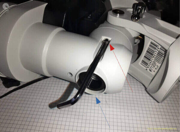
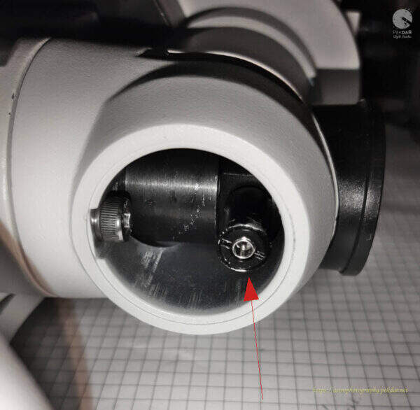
Remove the top inner screw using the right size allen key.

Remove the inner bottom bolt, that connects the two bodies using the right size allen key.
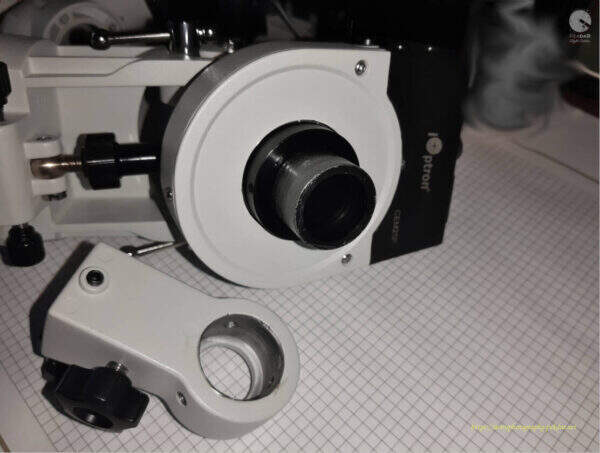
With one hand, grab the DEC body and the other hand, on the RA axle body. Moving from side to side with the DEC body, pull off slowly, until all is removed from the RA sleeve.
Remove the three allen screw head cap, securing the counterbalance bar holder.
Remove the holder. It fits very tightly, so a little force should be used to remove it.
Remove the three bolts, securing the RA axle gearwheel cover, using the right size of allen key.
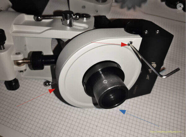
By hand, pull the cover off.
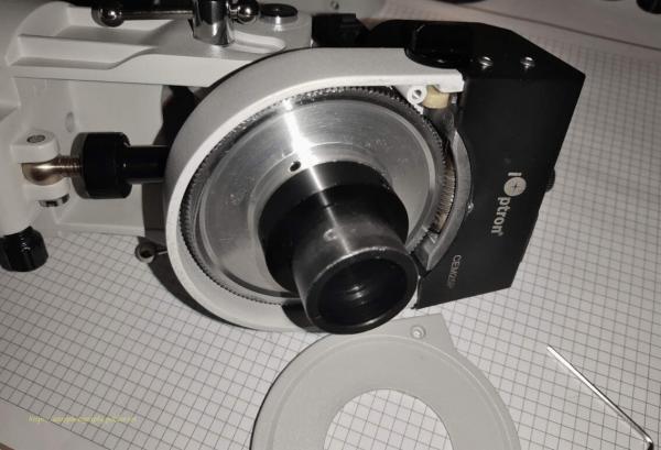
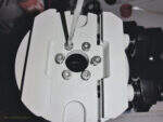
Remove the three screws securing the nut, that adjusts the pressure of the gear wheel to the bearing, using an allen key of the right size.
Unscrew and remove the nut.
Remove the three screws securing the RA axle gearwheel using the right size an allen key.
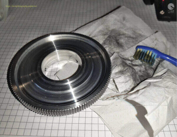
Remove the gear wheel.
Clean the gear wheel from old grease and possible fine dirt, using a small tooth brush. After collecting dirt, clean the tooth brush with a towel paper.
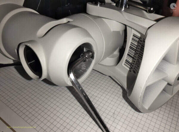
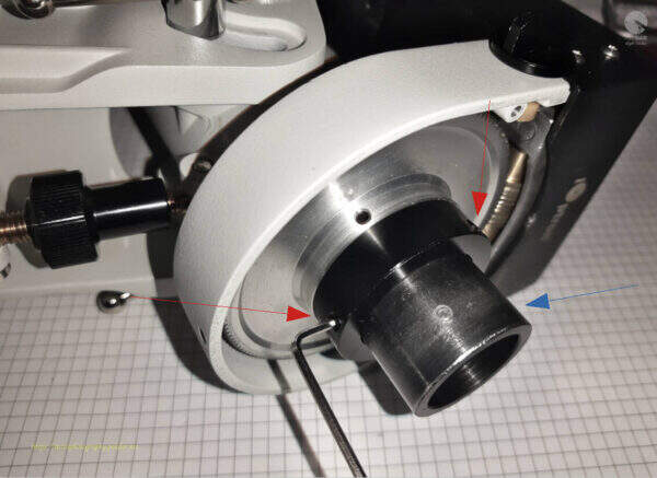
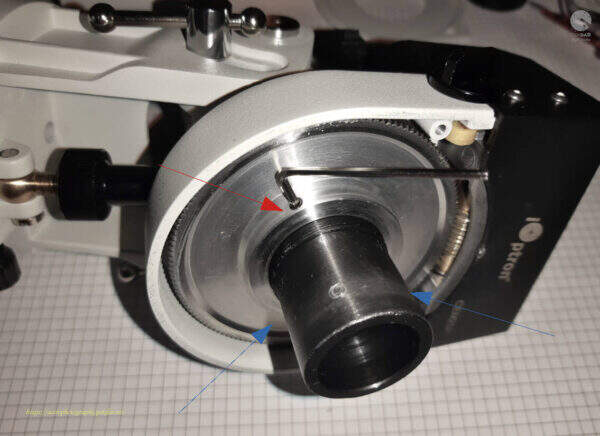
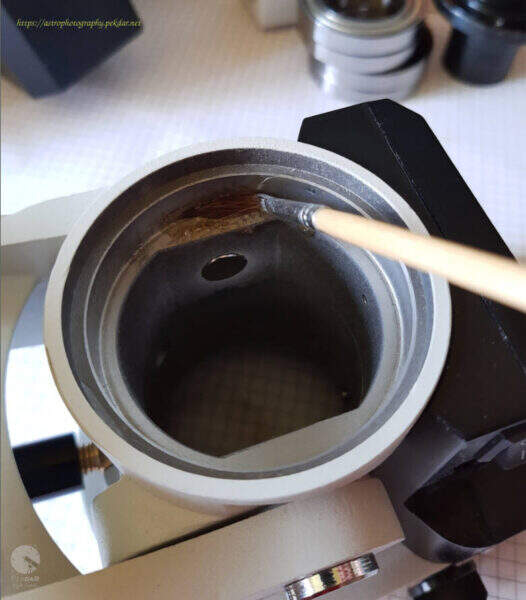
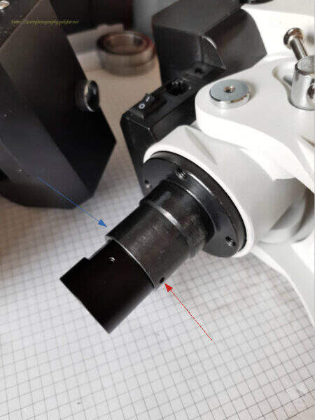
Apply a small amount of grease to the sleeve to slide the bearing off.
Grab the body with your hand and gently, with the hammer tap the edge of the sleeve.
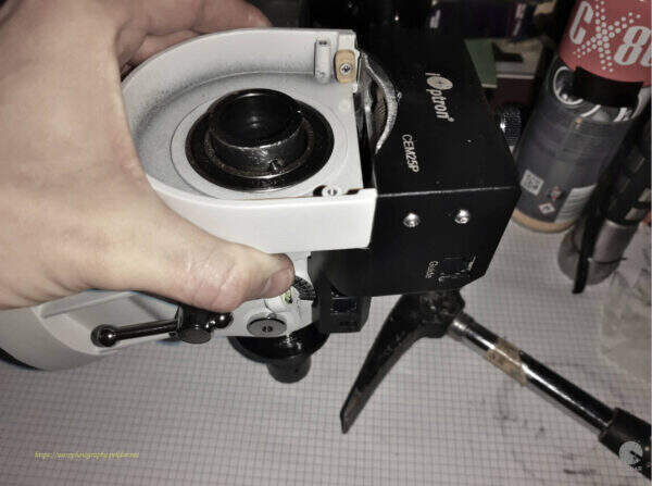
When the sleeve comes out of the bearing, the bearing can be removed from the body seat.
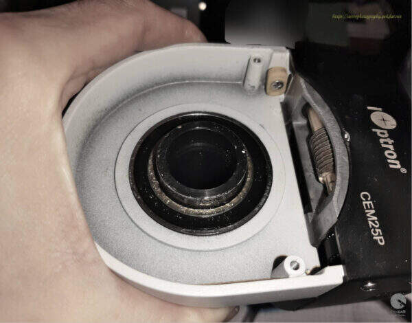
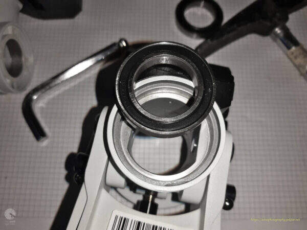
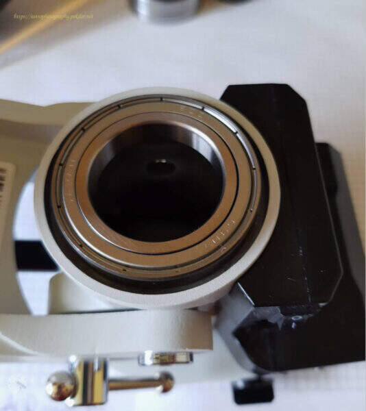
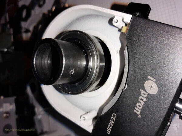
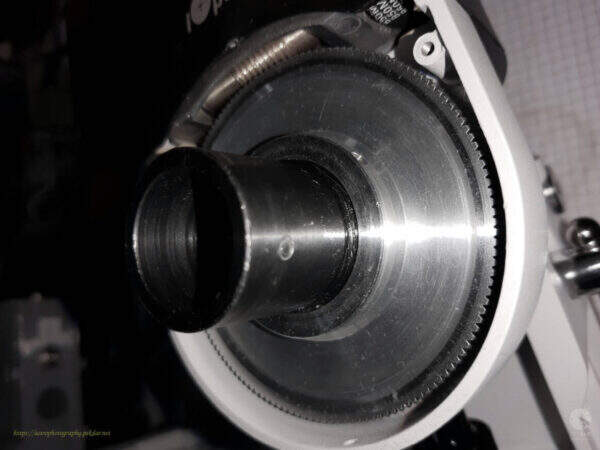
Inside the body, where the sleeve was, you can see the bearing that needs to be removed. It is placed quite tightly. Use gentle force to remove them. Use the largest size an allen key and a hammer, tapping lightly and evenly the edge of the entire bearing surface to extract the bearing.
The second bearing has been removed.
The photo shows both bearings that needs to be replaced.
Assembly of new bearings and RA axle components
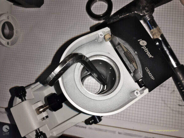
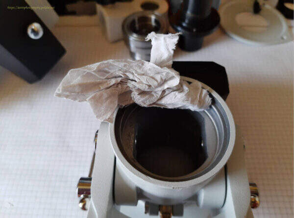
Before installing a new bearing, carefully clean the surface mounting points. A paper towel was used for cleaning.
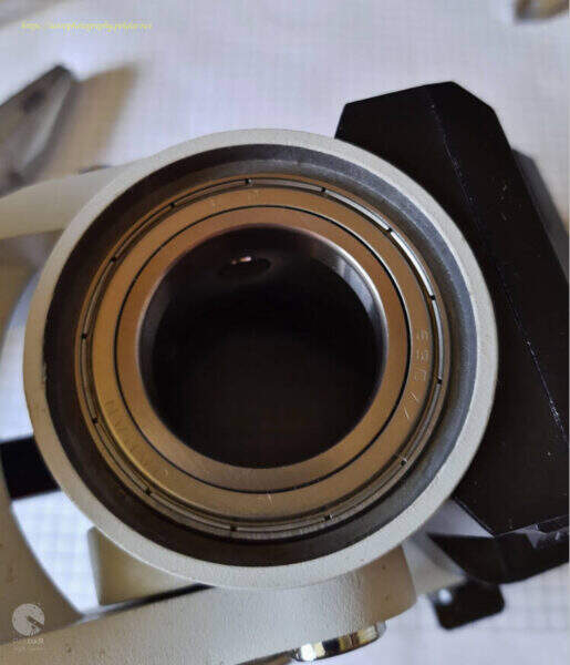
Apply a small amount of grease to the bearing seat.
Use a brush to spread it over the entire surface. This will make it easier to seat the bearing.
Seat the bearing and gently press down on the outer edge of the bearing, to push the bearing into the seat.
Precisely clean the RA axle sleeve with a paper towel and a cotton cloth or rubber. Make sure that there are no scraps of paper and other particles on the sleeve, that could later make a harder assembly.
Apply a small amount of grease to the sleeve and use a brush to spread it precisely over the entire surface.
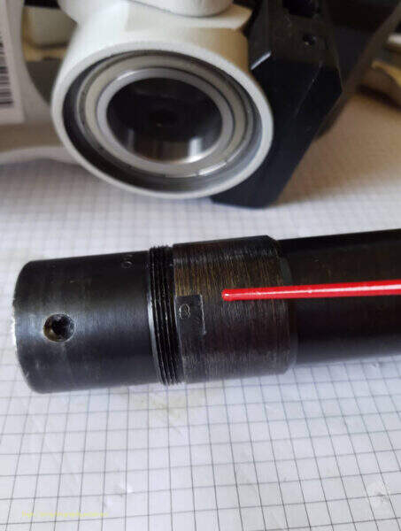
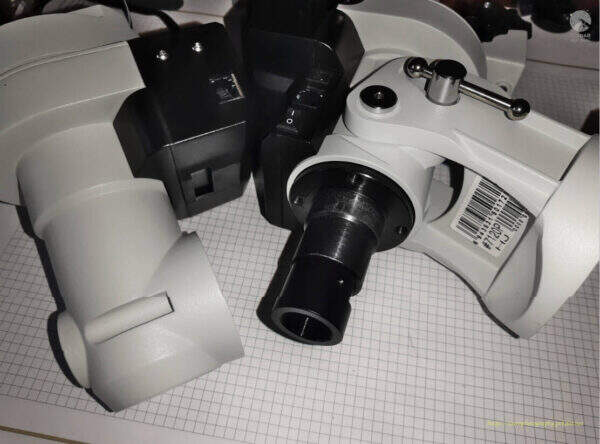
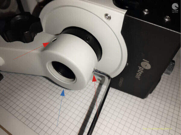
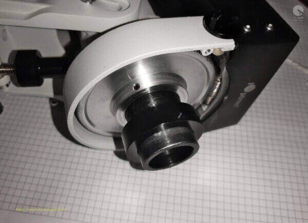
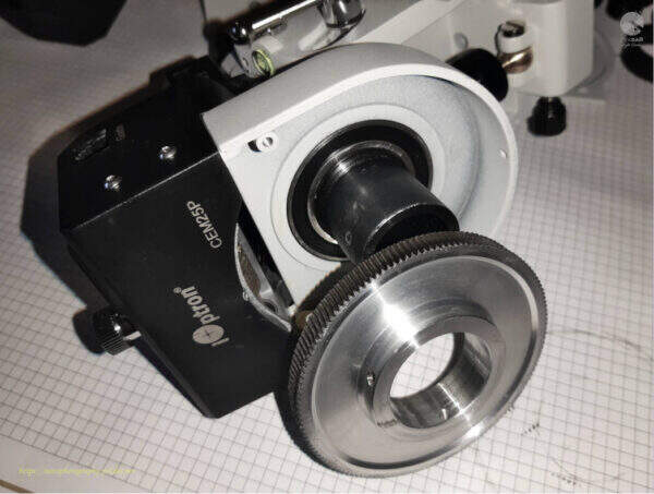
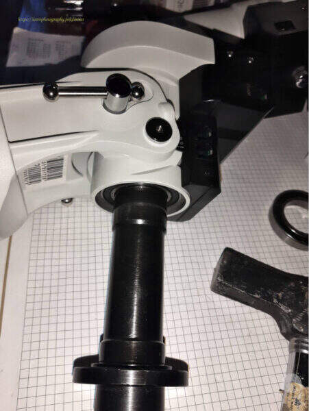
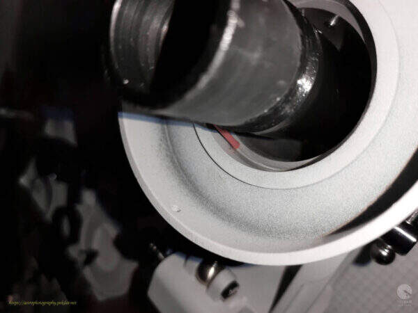
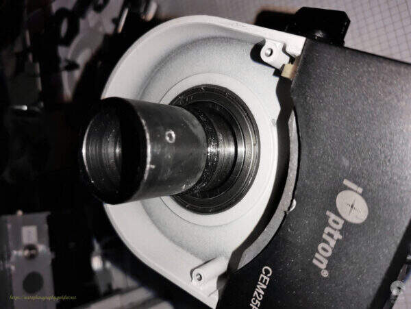
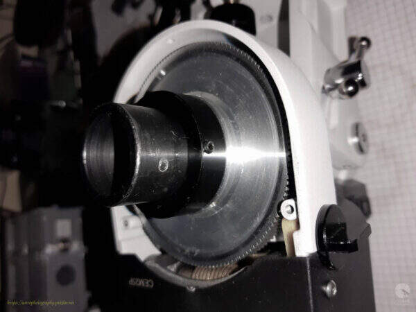
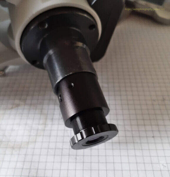
Slide the sleeve into the bearing seated in the mount as shown in the photo. Make sure you are installing the correct side of the sleeve.

You should tap lightly on the end of the sleeve, so that the whole passes through the bearing.

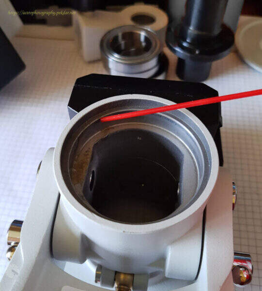
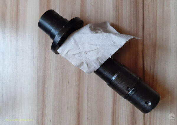
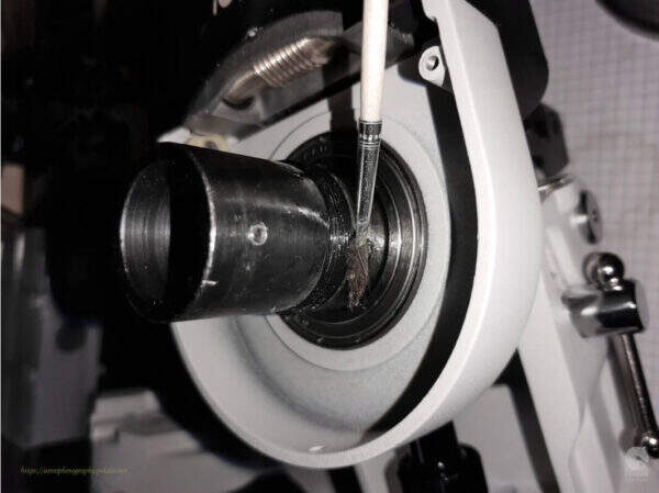
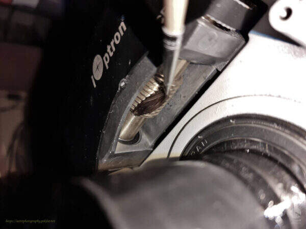
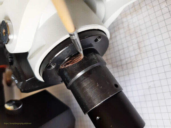
Clean the RA Axis worm with a small tooth brush and paper towel. Brush the dirt off with paper piece. This method is quite tedious but brings the intended effect.
Photo before cleaning.
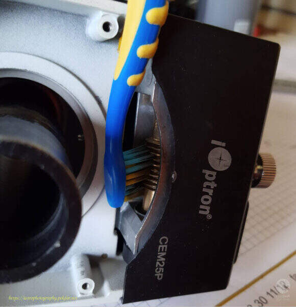
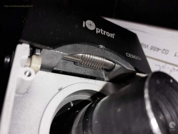
Photo after cleaning.
Apply a small amount of grease to the seat of the second bearing and use a brush, to spread it over the place, where the bearing will seat.
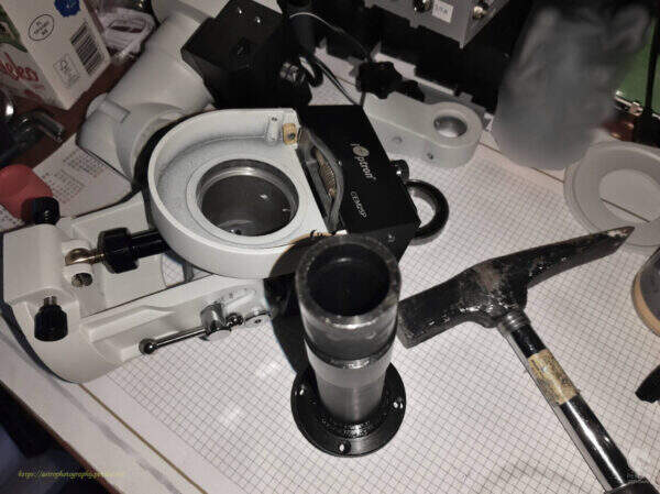
Install the second new bearing on the RA axle sleeve. Use sufficient force to push the bearing over the shoulder of the sleeve and insert it into the seat.
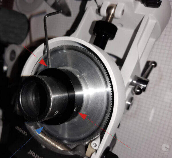
After seating the bearing in its housing, perform a simple test to confirm that the RA axis rotates without the slightest resistance.
Apply a small amount of grease to the sleeve, just above the bearing, where the RA axis worm gear will be installed.
Cover the RA axis worm with a little grease and a brush.
Install the RA axis worm wheel gear.
Install the black nut that adjusts the pressure force of the gear wheel. Screw it gently. The RA axle body should rotate around the sleeve very lightly and freely, without any noticeable resistance.
Use three hexagon socket screws to lock the nut. When tightening screws, resistance may occur as you twist the body around its axis. IMPORTANT: tighten the screws (lightly!), so that there is no resistance when turning the body around the sleeve axis.
Screw in the three allen locks and lock the sleeve. There may be unexpected resistance when rotating the body around the sleeve axis. IMPORTANT: Tighten the allen screws until there is no resistance.

Install the RA axis worm wheel gear cover and fasten with three allen screws.

Install the counter balance bar holder and lock it with the three allen screws.
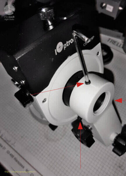
Put on the polar scope and lock it in place, by carefully tightening the two allen screws.
Screw in the polar finder lens.
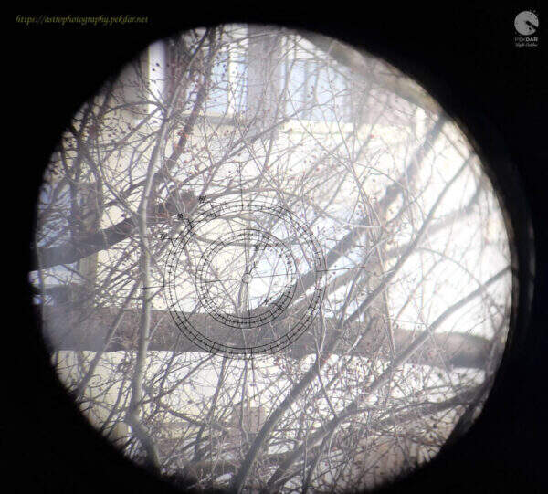
Remember to adjust the scope to the chosen, distant point, preferably a star.

EXAMPLE: a window corner on the opposite building was selected for this purpose. The photo of the polar target was taken with a phone, that is not perfectly aligned with the polar finder. Hence, the view of the shape of view is some what elliptical.
Apply a thin layer of grease to the RA axle sleeve.
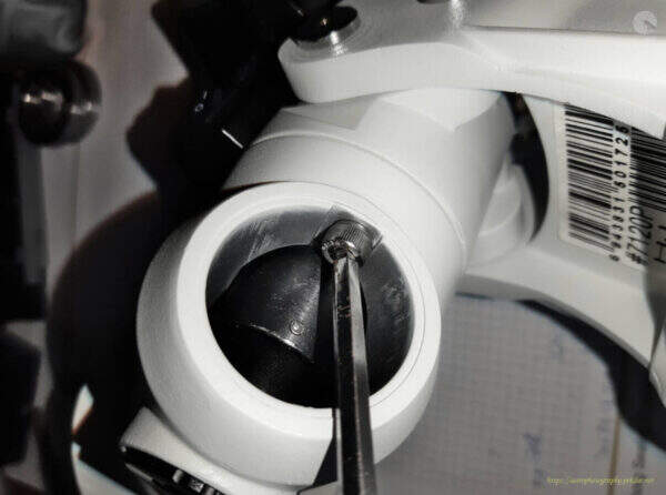
Insert the shorter screw into the other half of the body, on the inner part using the small angled pliers.

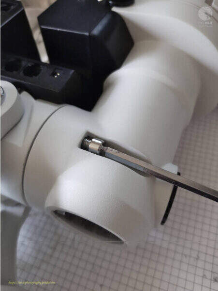
Put on the other half of the mount, in such a way that the screw inside, reach the appropriate hole. Grip the screw with a wrench and lightly screw it into the body.
Use the right size of allen key, to screw the second inner screw onto the body.
Screw the mount with the two, longer screws using the right size of allen key.
Attach the polar finder illuminator by hand or using small pliers.
Attach the cover by hand or with a pair of pliers.

Test to verify the appropriate of the bearings replacement
Attach the mount to the tripod. Attach the counter balance bar to balance the mount in the RA axis. Unlock the RA axis in such a way, that the mount starts to slowly rotate itself.