Zdobienie

IC 1805 (Heart Nebula) – H II Region and Stellar Wind Sculpting

Zdobienie

IC 1805 (Heart Nebula) – H II Region and Stellar Wind Sculpting

Anatomy of a Giant

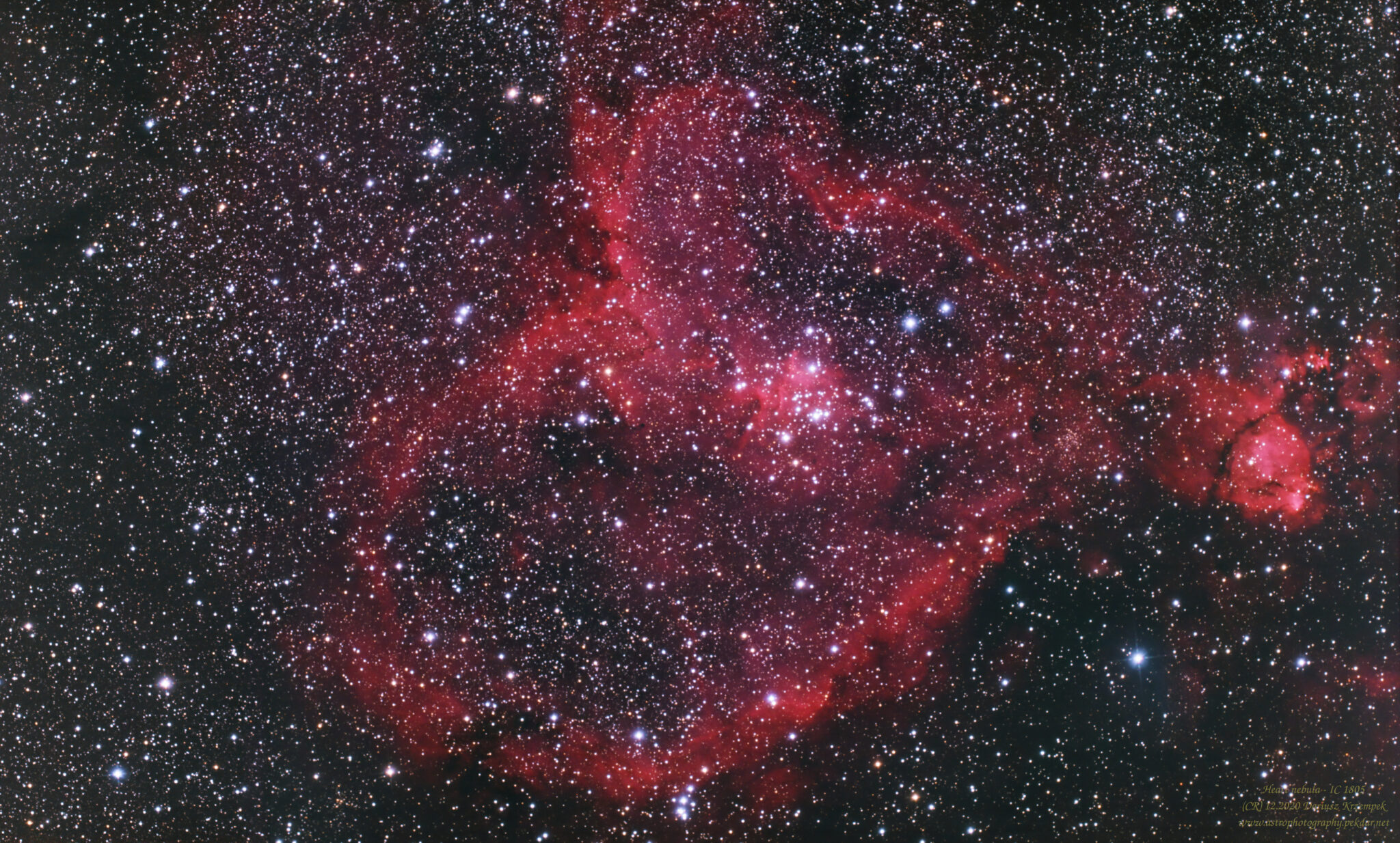
IC 1805, commonly known as the Heart Nebula, is in reality a vast star-forming region (H II region) spanning nearly 2.5 degrees across the sky (equivalent to five full Moons). Located approximately 7500 light-years from Earth in the Perseus Arm of our galaxy, this nebula is a classic example of the interaction between young, massive stars and their parent gas cloud.

The brightest part of the nebula (a knot at its western edge) is separately classified as NGC 896, because it was the first part of the nebula to be discovered. The nebula’s intense red output and its morphology are driven by the radiation emanating from a small group of stars near the nebula’s center. This open cluster of stars, known as Collinder 26 or Melotte 15, contains a few bright stars nearly 50 times the mass of our Sun, and many more dim stars that are only a fraction of our Sun’s mass.

The Engine

Melotte 15 The key to understanding this image lies at the very center of the nebula. The bright open cluster visible in the core is Melotte 15. It contains several ultra-massive O-type stars (with masses reaching up to 50 times that of the Sun). This is not a peaceful neighborhood. These stars emit powerful stellar winds and intense UV radiation.

  • Excavation: The stellar wind has literally “blown out” the gas from the center of the nebula, creating the characteristic void around the cluster.

  • Ionization: UV radiation strips electrons from hydrogen atoms in the surrounding cloud. When these electrons recombine (drop to lower energy levels), they emit photons at a specific wavelength – primarily the H-alpha line (). It is this physical process that accounts for the deep red color dominating the image.

Dust Structures and “Elephant Trunks” Contrasting with the bright hydrogen plasma, dark lanes of interstellar dust (silicates and carbon) are visible in the image. Note the pillar-like structures (often called “elephant trunks”) pointing towards the center. These are denser pockets of gas and dust that are resisting the destructive force of the stellar wind from Melotte 15. Inside these dark cocoons, processes of gravitational collapse are still ongoing – new stars are being born there.

Technical Aspect

Capturing IC 1805 required a camera sensitive to the H-alpha band or a modified DSLR/Mirrorless, as standard infrared cut filters in consumer equipment block most of the signal from this object. Due to its enormous angular size, this image required either short focal length optics or a mosaic technique.

On the left side of the photo you can see an interstellar dust (grey, dark grey).

The photo is the result of combining two different photo sessions but in the same location. The frame is not proportional, it is too wide. However, I didn’t want to crop it because of the interstellar dust revealing on the left side of the frame. Personally, I liked this photo very much and I think it is better than the previous one, which was made only from one photo session.

IC1805

IC 1805 – Heart Nebula

Source: https://en.wikipedia.org/wiki/Heart_Nebula

Technical information

  • Date: 12.2020
  • Composition: APP
  • Processing: APP + RT + GIMP + add-ons (Linux)
  • Total exposure time minus defective light frames: 4h 36min.
  • Lights: 276
  • Calibration frames: Flats, Bias, Darks
Support my work on Ko-fi

Did this guide help you?

I create these guides and projects as a hobby. If I helped you save time or money, consider supporting my work with a coffee. It keeps the energy flowing for future projects.

Categories
Newest articles

iOptron CEM 25P

iOptron CEM 25P RA axle bearings replacement

iOptron CEM 25P RA axle bearings replacement. Instructions for how to replace faulty RA-axis bearings (6907) in the iOptron CEM 25P mount yourself. Eliminate friction and improve tracking accuracy. Do…

Support

Was description useful? Consider to support author, it prevents to post annoying ads for you. All you just could do is once a year, sponsor for me a coffee. The currency, amount, doesn’t matter to me. Matter to me, that you want!

Read

Similar Articles

SynScan controller firmware update

SynScan controller firmware update – NEQ6Pro

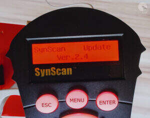
WARNING – the author of this manual accepts no responsibility, for any damages that may occur as a result of following this manual. All actions described in this manual are undertaken at your own risk. SynScan controller firmware update – Introduction   Starting from version 3.0, users can independently update the firmware of SynScan controllers for NEQ mounts. Simply download the latest software version from the Sky-Watcher website and perform the update following the instructions provided here. Requirements SynScan™ Hand Control of version 3.0 or later. Windows 8.1 or later An available RS-232C communication port on the PC RS232-USB hardware converter in case of missing DB9 COM port in your laptop / PC PC link cable that comes with the SynScan™ hand control DC power supply with 12~14V/1A output. Power plug should be 2.1mm diameter, tip positive.      Preparation for update Create a directory called SynScan, preferably on your C: drive. Visit the Support Page of the Sky-Watcher website at https://www.skywatcher.com/download/software/ Download and save two files, follow with example: Windows program: SynScan Firmware Loader, Version 3.5 – click with Download button. you’ll save a file with name: synscan_verXXXXXX_firmware_release.zip where XXXXXX – is a version nr Next download Firmware: SynScan V4/V5 Hand Controller For All GO-TO Mounts, Version 4.39.21 – click on Download button you’ll save a file with name: synscanfirmwareloader_verXX.zip where XX – is version nr Connecting devices Connect the USB-COM (RS232) adapter to the computer’s USB port.   Connect the male COM plug of the adapter to the female COM plug of the SynScan controller cable.   Connect the RJ-11 plug of the controller’s COM cable to the RJ-11 port on the controller. Ensure that the plug is securely inserted—you should hear a distinct “click” as the plug snaps firmly into place in the controller’s socket.   Connect the controller to the mount using the dedicated cable – RJ45 plug to the COM port on the mount. Ensure the cable is securely connected to both the controller and the mount for proper communication during operation. We now have the following connection setup – example:   Firmware update the SynScan™ Hand Control On the controller, simultaneously press and hold the buttons “0” and “8.” Turn on the mount’s power as shown in below photo. The controller will emit a “beep” sound during startup and then display the message “SynScan Update Ver….” as shown in the image. The controller has now been set to firmware update mode. This indicates that the device is ready for the next steps in the firmware update process. On your computer, run the Computer Manager and find the COM port which will be used for update. With this example it is COM5. Check the COM port number on your system. Open Computer Management and locate the COM port. To do this on a Windows system: Press Win + X and select Computer Management from the menu. In the Computer Management window, navigate to Device Manager. Expand the section labeled Ports (COM & LPT). Here, you will see a list of available COM ports along with their assigned numbers (e.g., COM1, COM2). With this example it is COM5. Run the SynScanFirmwareLoader.exe software on your PC. Once the program is launched, you should see a window SynScan Firmware Loader , make sure the “Auto-detect COM Port” checkbox has been unchecked. Set the COM port. Click the HC Version button. The program will attempt to connect to the controller and retrieve information about the hardware version, firmware, and the celestial object database. You will see the version numbers at the bottom of the Firmware Loader as shown on below picture. If the program is unable to communicate with the controller, enable the Auto-detect COM Port option and click the HC Version button again. If the Loader program cannot detect an available COM port, check the connection between the controller and the computer. Click Browse to select the SynScanVXXXX.ssf file in the SynScan folder. It is recommended to enable the – Enforce database update – option and then click the Update button to start the update procedure. This ensures that the entire database is refreshed during the update process, reducing the risk of any errors or omissions. The update status can be monitored under the Update and HC. Version buttons. Update Complete. Click on the HC. Version button and check if the controller has reported a new Firmware version. The update was fully successful. Close the Loader program and turn off mount power suppl. Turn the mount’s power back on and check whether the controller displays the new firmware version. Check if the mount and H.C. works properly. As you can see, the firmware update process for the SynScan V4 controller is not overly complicated, but it does require careful attention. It’s crucial to follow all the steps outlined in this guide in the correct sequence, with focus and precision. I hope the description provided could be at least somewhat helpful.   It’s worth mentioning that the mount performs excellently in the field when used with the PERUN II power bank.

Read more...