Zdobienie

External Power Supply for Laser Collimator modification – Practical DIY Guide

Zdobienie

External Power Supply for Laser Collimator modification – Practical DIY Guide

Laser Collimator modification: The Button Cell Problem

Standard laser collimators (including the popular Baader Mark III) are powered by small LR44 or CR2032 button cells. These have two critical flaws in astrophotography:

  1. Voltage Drop in Cold Weather: In freezing temperatures, their efficiency drops drastically, causing the laser to dim. A dim beam loses its definition, making it difficult to precisely judge the center of the mirror.

  2. Short Lifespan: Batteries tend to die at the worst possible moment, and changing them in the dark risks mechanical shock to the collimator itself.

Engineering Solution: Constant Power Source

The goal of this modification is to replace the unstable chemical source with an external power supply [Describe briefly what you used: e.g., a 2x AA 1.5V battery pack or a 3V DC adapter]. This ensures constant laser spot brightness throughout the night, regardless of ambient temperature. Consistent voltage guarantees a sharp, focused beam, which is crucial for the precision of Newtonian optics alignment.

Warning:

Cable Drag Introducing a wire to a device that must remain perfectly axial involves mechanical risk. The weight or stiffness of the cable can cause slight flexure in the focuser drawtube or tilt the collimator itself within the sleeve.

  • The Solution: The wire must be lightweight and flexible. It is essential to support the cable (strain relief) by attaching it to the telescope tube (e.g., with Velcro) so that it exerts zero torque or pulling force on the collimator. Ignoring this physics principle will lead to false collimation readings.

The photo below shows a socket for three pcs of the SR batteries.
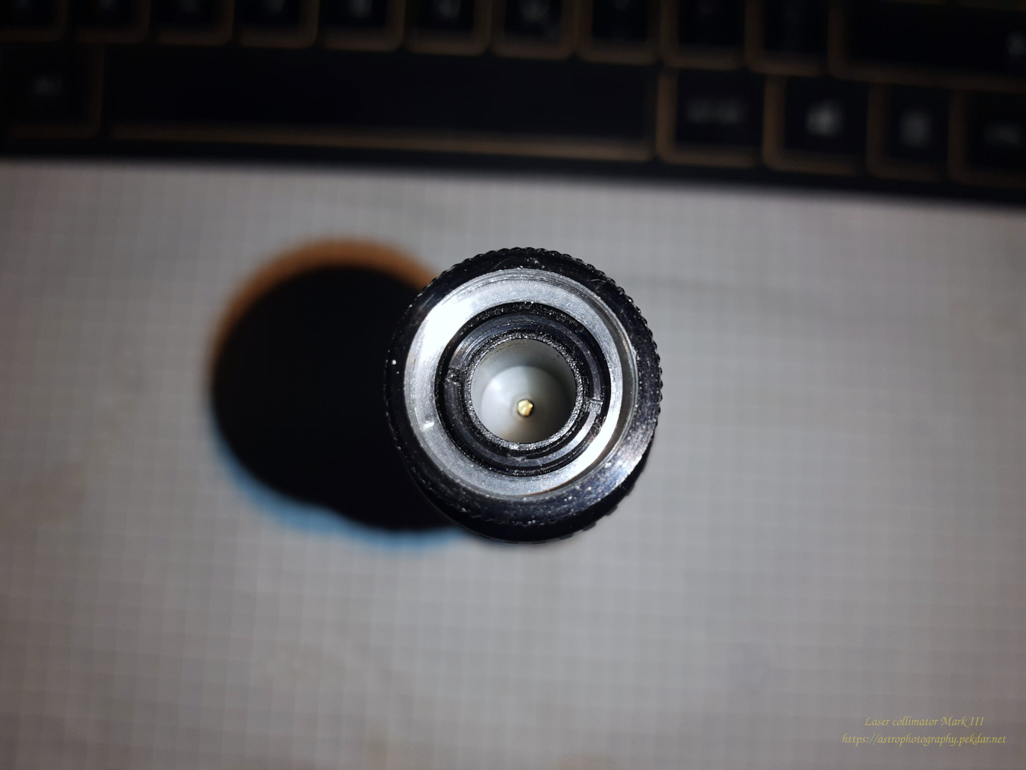
gniazdo na trzy sztuki baterii typu SR
socket for 3 pcs of SR battery type
 
   I decided that I would modify the power supply of my collimator, so that I would have easy access to popular and commonly available LR03 / AAA batteries or rechargeable battery. This is how my tiny-project with modernization of the power source of my collimator was created. More you can find below.
 

Necessary tools and items 

  • 1x self-designed and made battery cartridge,
  • 2x screw with a cross head, dimensions of 3.85 mm fi head, 2 mm fi metric thread,
  • 1x inner washer. dimension fi 2mm
  • a pair of wires with a section of 0.8 mm – external dimension,
  • 1x DIP switch (on/off),
  • 1x 3mm red LED (1.9-2.1VDC, max: 20 mA)
  • 1x 270 Ohm resistor, 250mW
  • 1x self-designed and made housing for the set of 3x AAA rechargeable battery / battery,
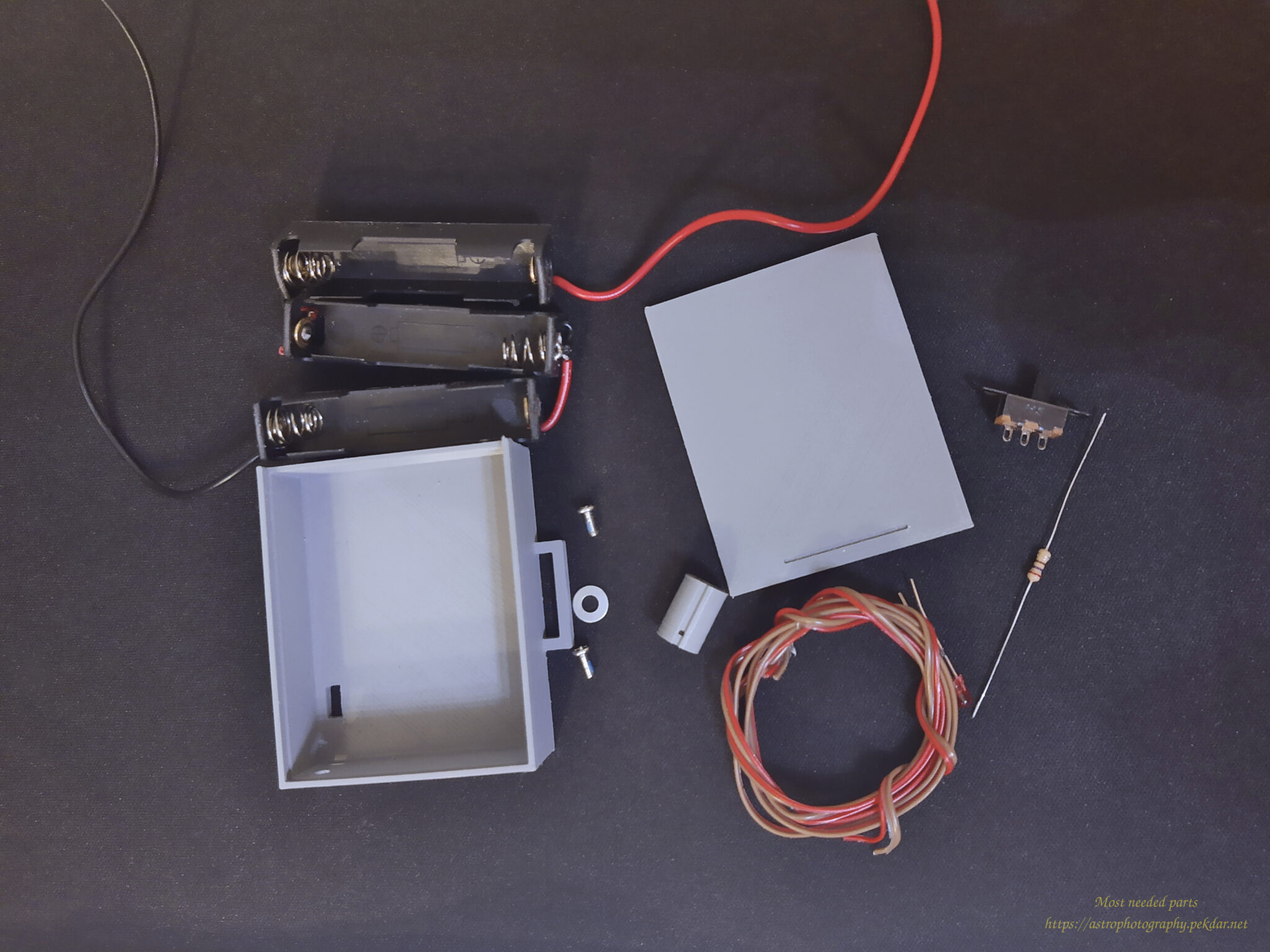
Potrzebne rzeczy
Set of needed items
 

Blender

   The location of the battery in the collimator looks like a small sleeve shape. Originally there are 3 pcs batteries, model SR. I’ve measured the place and in the Blender program I designed a cartridge that will act as a connector for power supply cables and provide good wire contact.

   With my example, I used 3 AAA rechargeable battery. The battery voltage is slightly lower (1.3 VDC) than the standard LR03 / AAA battery. Lets count:

3x rech. batt. AAA = 3,9VDC

Collimator with standard requirements to work needs:

3x SR 1,5VDC = 4,5VDC

   The voltage difference is 0.6VDC it can be a lot, or not much, it depends on how you look at it. It’s just a laser, lower voltage will cause lower laser brightness but won’t prevent you from using it. The standard alkaline batteries with a voltage of 1.5VDC / piece provide the collimator factory voltage.


In order to be able to easily remove the batteries for charging, I used battery cradles. I thought it would be good to equip the power module with a DIP switch and a red LED, that would indicate the module’s operation. I have designed a housing that will fit all these things. The lid of the housing is sliding, so I can easily get inside to replace the batteries. The housing has a small handle in the shape of an ear through, which you can thread Velcro fastener. It will be possible to easily attach the power module to any mounting or telescope handle location, so that it does not prevent collimation process.

Blender 3D model
Blender 3D model
 

The photo below shows the printed models. Battery cartridge and a box with a lid.
 
Wydrukowany wkład bateryjny oraz pudełko z wieczkiem
3D printed battery supply and battery box with cover
 

It took me a while to figure out a way, to lead the power cables to the battery cartridge. After considering several options, I concluded that the best solution would be to drill a small hole in the laser power cap.
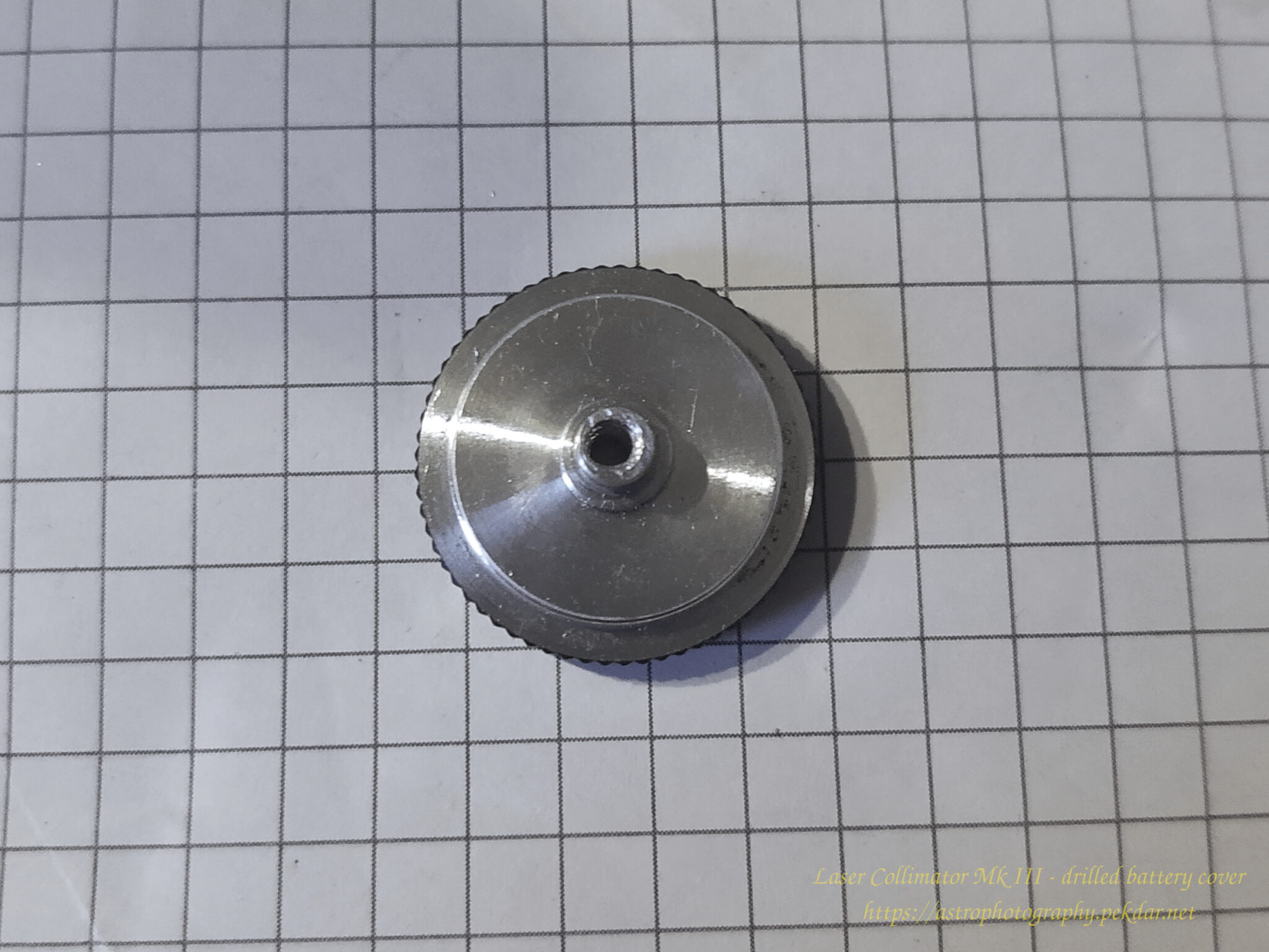
 
otwór w wieczku zasilania lasera
A drilled hole into a over
 

I threaded two wires through the drilled hole.
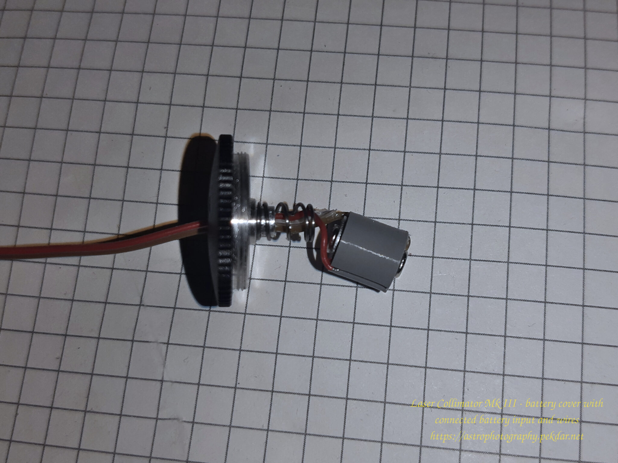
przewleczone przewody w wieczku
 

Let’s put it all together

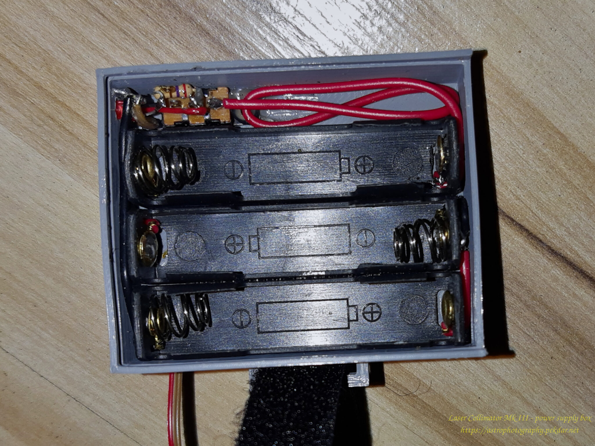
  I’ve connected three battery cradles in series with the electric cable, which is included in the set as a standard. I checked the quality of the connections with a multi-meter. I glued the sockets with the “droplet” glue to the bottom of the box. Next to the sockets, I screwed the power switch (DIP) and put on the red LED, the anode (+) of which I connected to the resistor and its corresponding to the switch pin. I’ve connected the cathode to the negative pole of the power circuit. By turning on the power to the entire system, I also power the LED diode, which signals the operation of the entire system.
Laser Collimator MKIII - Power supply box
Laser Collimator MKIII – Power supply box
 

I screwed the two ends of the wires to the battery cartridge. The negative from the bottom and the positive inside and locked it from the top with the screw, which is also the positive pole for the laser housing.
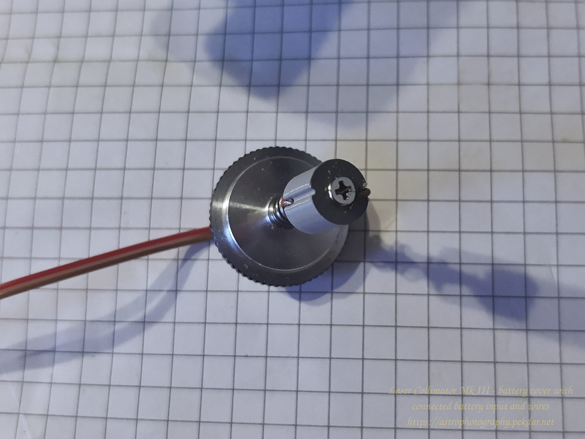
battery cartridge
battery cartridge
 

I have inserted the battery cartridge into the place, where the batteries would normally be. Gently pressed a screwdriver on the top of cartridge, so that the screw on the front of the cartridge had good contact, with the negative pin of the power supply. I screwed the lid, where its spring pressed against the screw washer together with positive power cable where it was connected.
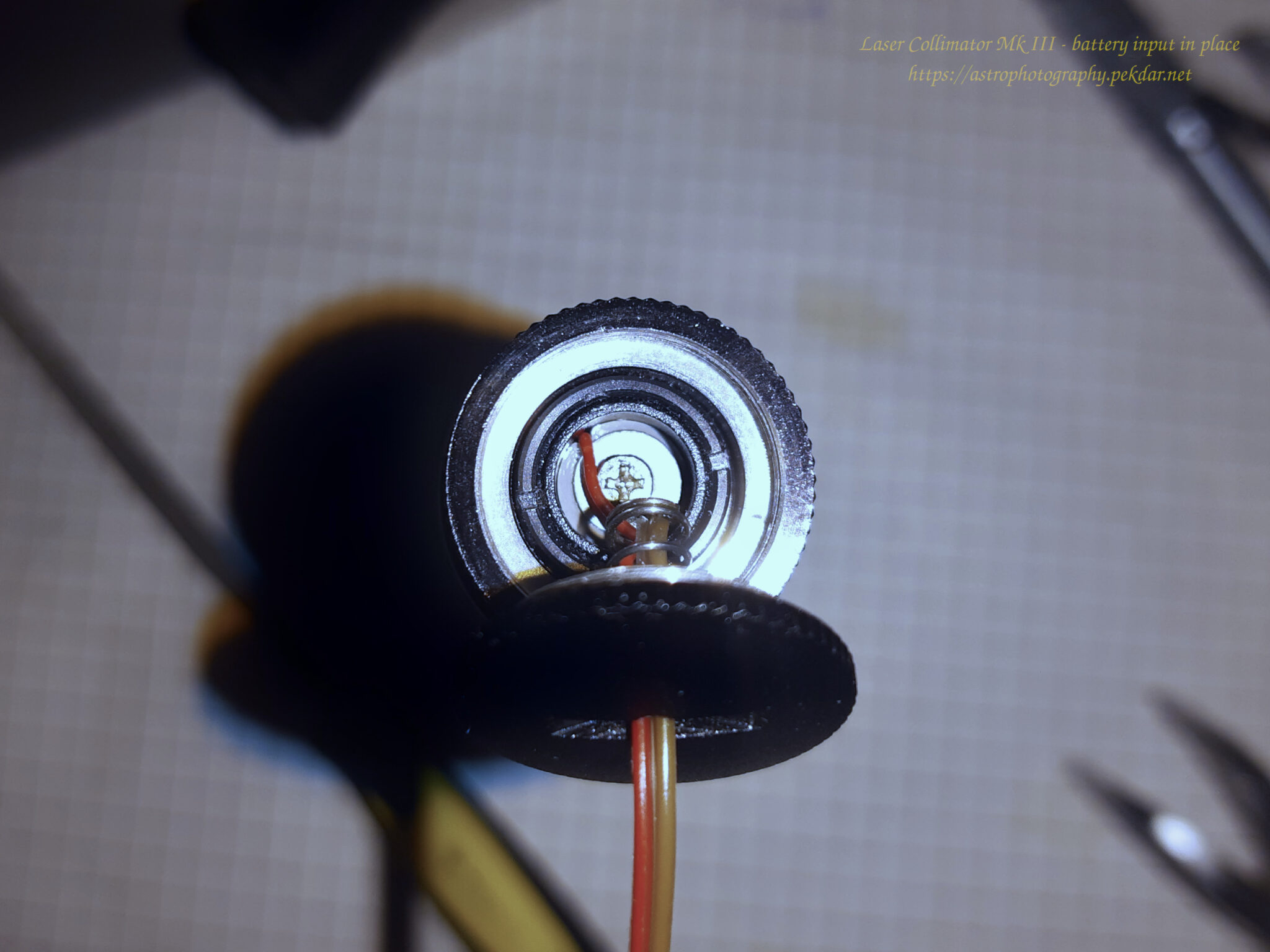
 
battery cartridge in the battery socket
 

Tests

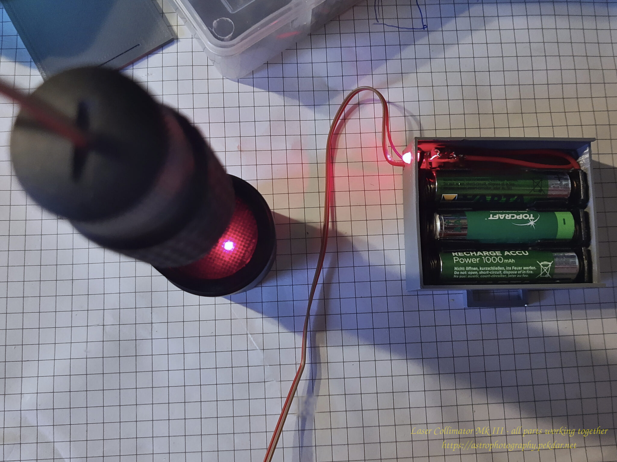
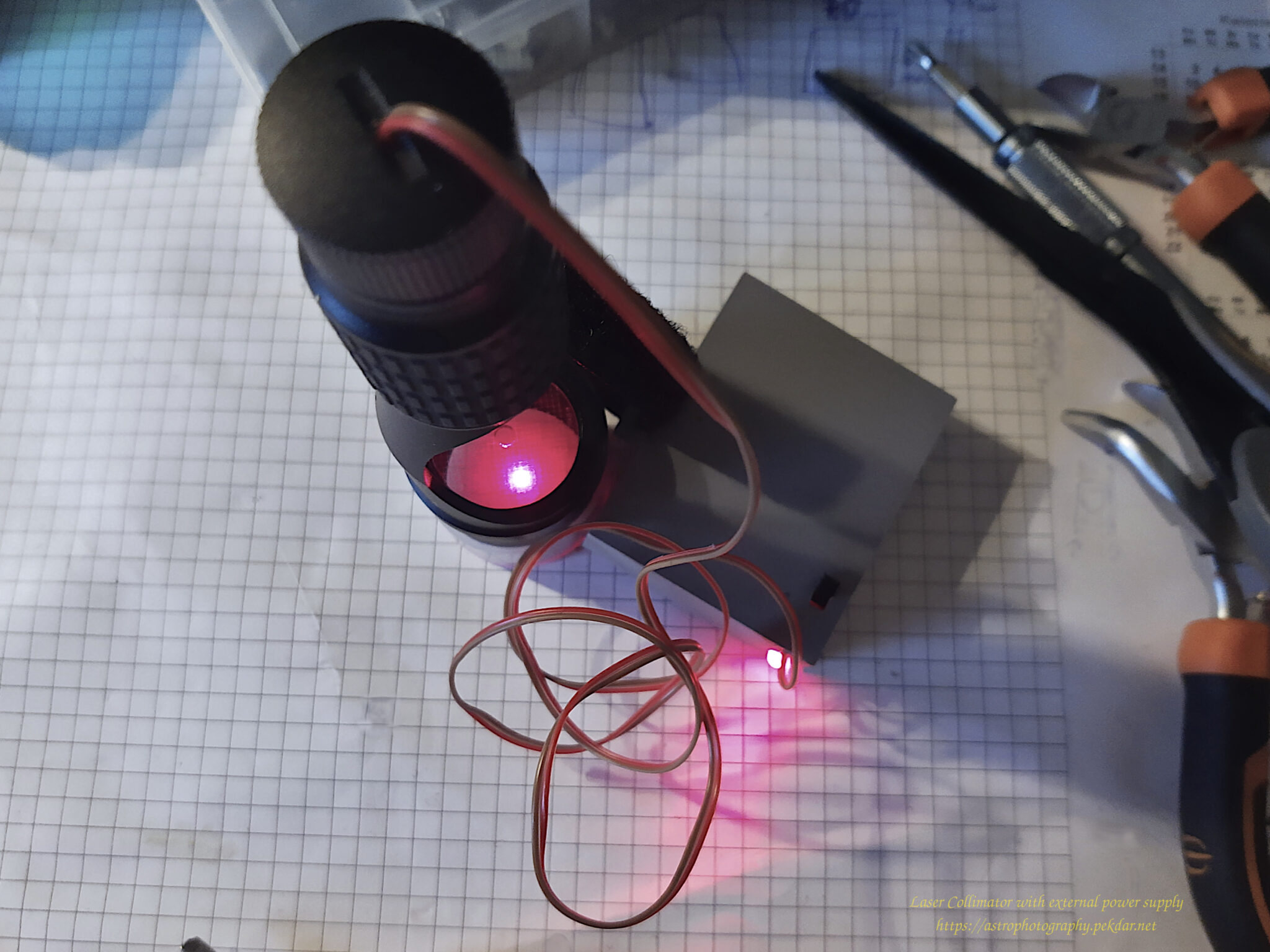
   Let’s check if it works. I’ve put on a 3x AAA rechargeable battery and turned on the power. The LED status flashed a beautiful red light. For a moment I watched if there would be some unwanted smell of burning electronics and searing smoke with my eyes…. Luckily, nothing like that happened. I turned on the laser and a beautiful red beam of focused light appeared on the top of my desk.

It works!
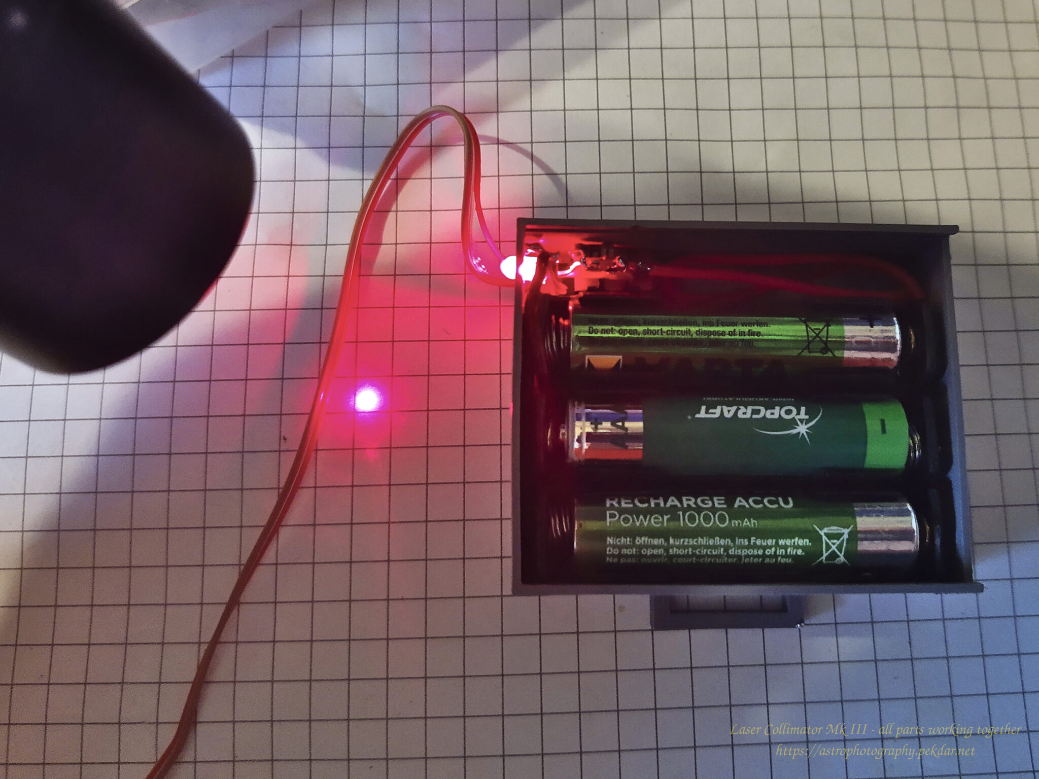
 
assembled prototype testing
 
assembled prototype testing
 
assembled prototype testing
 
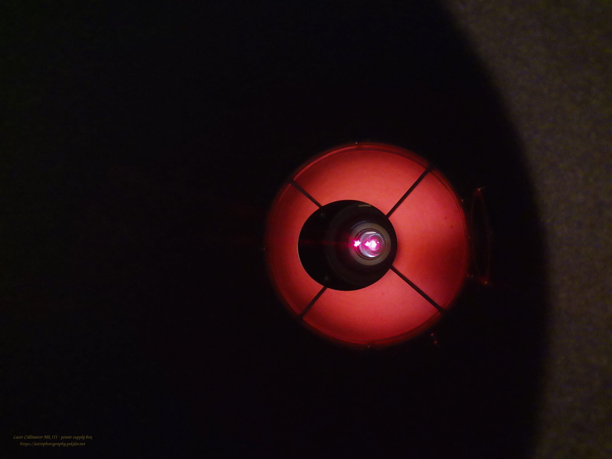
Laser Collimator Mk III in action
Support my work on Ko-fi

Did this guide help you?

I create these guides and projects as a hobby. If I helped you save time or money, consider supporting my work with a coffee. It keeps the energy flowing for future projects.

Categories
Newest articles
Support

Was description useful? Consider to support author, it prevents to post annoying ads for you. All you just could do is once a year, sponsor for me a coffee. The currency, amount, doesn’t matter to me. Matter to me, that you want!

Read

Similar Articles

SynScan - PCB - pads

SynScan GOTO controller – trouble with buttons

Even though this article has been around for ages, it still offers valuable insights and practical support for users of the SkyWatcher NEQ6Pro mounts. The content has been refreshed and tailored to match the current website engine, making sure everything looks and runs as smoothly as possible.     At some point while using the controller, I noticed that the ESC button wasn’t always working. I lived with it, but after a while, the left Ra button also started acting up and wouldn’t always connect. A red flag went up in my head – something needed to be done. It’s worth noting that the problems appeared right after the warranty period ended… coincidence? There weren’t many options, just two: either send the controller for service and pay a considerable amount for the repair, or try to fix it myself. My tinkering nature took over (as always), and I set about solving the problem on my own. I assumed that some dirt or substance must have gotten inside, which over time became sticky and was gripping the button. I don’t recall spilling any liquid on the controller, but I also can’t rule out a situation where rain or high humidity (fog) penetrated the controller’s interior. My recent, not-so-great experiences with electronics, especially those manufactured in China, gave me an idea of what I might find inside, so I prepared a few things for the job. Contact spray – quite a nice product for cleaning and degreasing electronics and optical devices, including removing contaminants from glass without damaging optical coatings.Cotton swabs are a must-have. Plastik 70 spray – in my electronics work, I usually reach for Plastik 70 spray (clear lacquer). It creates a thin, transparent, and, most importantly, sealed coating. It excellently protects soldering points from the tin components oxidizing and forming ‘cold solder’ joints, which stop conducting electricity relatively quickly after service work.A small, so-called artistic brush will be necessary to precisely and evenly spread the Plastik 70 over the repaired surfaces. Let’s get to work. We’re unscrewing the controller; it’s held together by 4 Phillips head screws. There are no clips, so slowly and gently, but without excessive force, we remove the housing. On the left side, carefully disconnect the white ribbon cable (signal) with the white plug and the plug with the colored wires (power). Grab the PCB board from the left side and slowly, gently turn it over to the right side. Contamination is visible at the soldering points of the white ribbon cable. Below, you can see dirty pads for the ESC button. Now I know where the problem with the uneven operation came from; it would connect sometimes and sometimes it wouldn’t – irritating. It’s not that visible in the photo, but the direction button pads weren’t exactly clean either. It was quite noticeable under the light. The opposite end of the controller, was also dirty. The soldering points of the disconnected plugs. The button pads were also dirty. I’m at my wit’s end. There’s no choice, the entire PCB will have to be cleaned. How to clean without breaking anything? Spray a little of the substance into the removed cap from the contact cleaner and dip a cotton swab in it. Lightly wipe out the dirty areas. Repeat the process until all the dirt is removed. Once you’ve cleaned all the areas, you need to protect the soldering points. Plastik 70 and a brush will be used for this purpose. The procedure is very similar to cleaning. Spray a little of the substance into the removed cap. Use the brush to apply the Plastik 70 to the soldering points. Wait 10 minutes for the applied Plastik 70 to dry.” View of the controller after cleaning the soldering points of the electronics, pads, and applying a protective plastic coating to the soldering points: I think it turned out quite decently. In my assessment, that’s everything. All that’s left is to reassemble the controller and test its operation. The problems that occurred earlier have disappeared.    

Read more...
EQDIRect for NEQ and EQ mounts

EQDIRect for NEQ and EQ mounts

    The GOTO controller is extremely convenient and practical to use, when you want to look at interesting night sky objects, with your own eye through the eyepiece mounted in the telescope’s focuser. The ability to quickly select an object using the GOTO controller, is invaluable. It’s way better using mount with PC and Here it comes the EQDIRect for NEQ and EQ mounts.     In astrophotography, however, the GOTO controller isn’t necessarily as convenient. I admit there were times when it actually got in my way. I decided to remove the controller so it would no longer intermediate the mount control; its role has been taken over by Astroberry combined with an EQDirect solution. My own implementation is based on descriptions for EQDirect available on the Internet. EQDIRect self made    The topic seemed simple, however, when it came to actually building the device myself, things weren’t so obvious anymore. Some important information is missing online. It’s easy to make a mistake that could seriously damage the mount’s electronics, as well as the Astroberry or another computer to which the EQDirect is connected. Repairing these devices can be very expensive! Once I had gathered all the necessary pieces of the “puzzle”, analyzed and double-checked the subject several times, I assembled the whole thing. Then, with a slightly trembling hand, I switched on the power to the mount. EQDIRect home made – set Luckily, nothing exploded 😉 What’s more, everything works – and it works like a charm! The mount responds to and executes all commands issued to it by the KStars+EKOS duo, along with the EQMod with INDI driver, and all of this resides together in Astroberry. EQDIRect for NEQ and EQ mounts – Astroberry configuration EQDIRect – EKOS – EQMod mount driver with setup Of course, EQDIRect will also work with ASCOM and other software that requires such a technical solution to control the Sky-Watcher EQ6, NEQ6Pro mounts. EQDIRect – EKOS – EQMod mount driver connection setup EQDirect with testing setup It works really well, even in slightly freezing conditions – tested – see the attached photos 🙂 To protect the expensive mount from damage, my EQDIRect unit is equipped with several additional electrical protections. Mount performs excellently in the field together with EQDirect when used together with PERUN II power bank. If you are interested in acquiring EQDIRect made by me, please don’t hesitate to reach out me by filling out the contact form.

Read more...
Rosette Nebula - NGC 2237 - Caldwell 49

Rosette Nebula NGC 2237 – Caldwell 49

Rosette Nebula NGC 2237.
In this article, I have gathered in one place the most interesting information about the entire nebula and its selected regions. The information contained in this content is my own compilation based on collected data.

Read more...